


Part 3 - Interface
In the Navigation Panel section, you will learn where various parameters are displayed on the ECDIS software panel. Knowing the location of these parameters is crucial for quick access to essential information during navigation. In this section, we will take a detailed look at each element of the panel so that you can efficiently find and use the required data.
3.5. Navigation Panel
>
>
The currently examined element is indicated by a green outline and numbering. Explanations will be provided in this window. After reviewing the information, click the 'Next' button or follow the instructions. If you wish to go back to the previous step, click 'Back'. If you decide to finish the study prematurely or choose another section, click 'End'.
Message
0

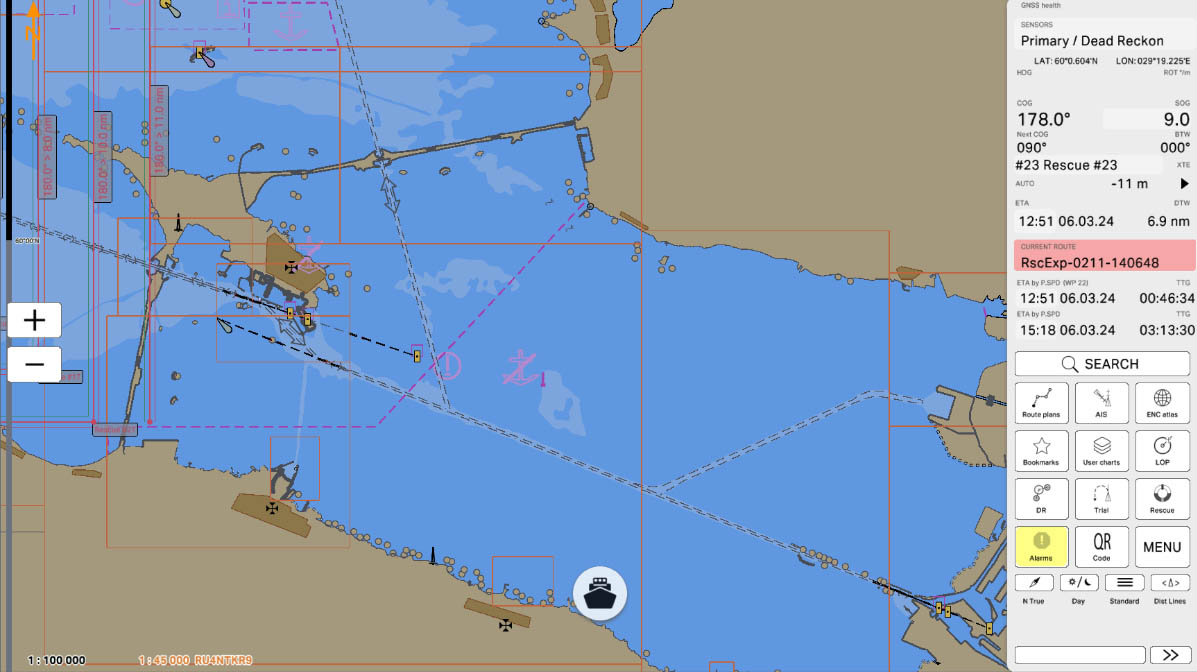


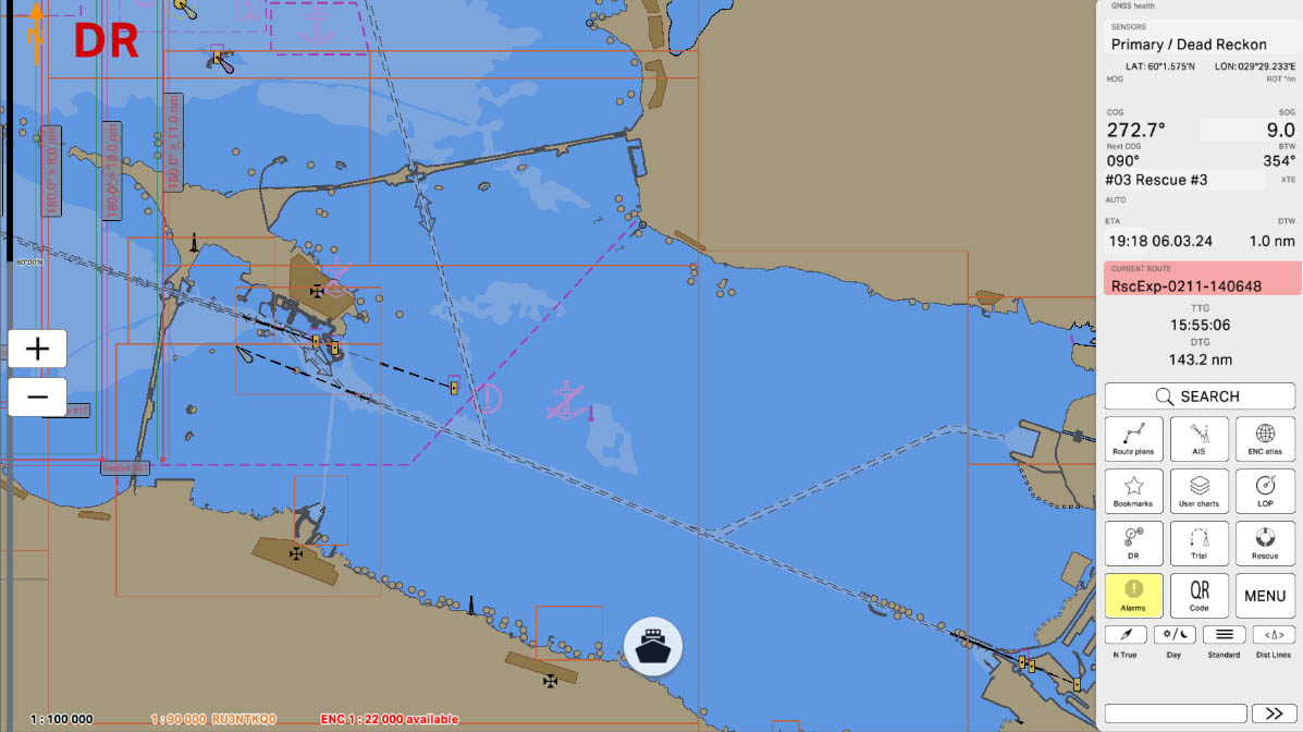
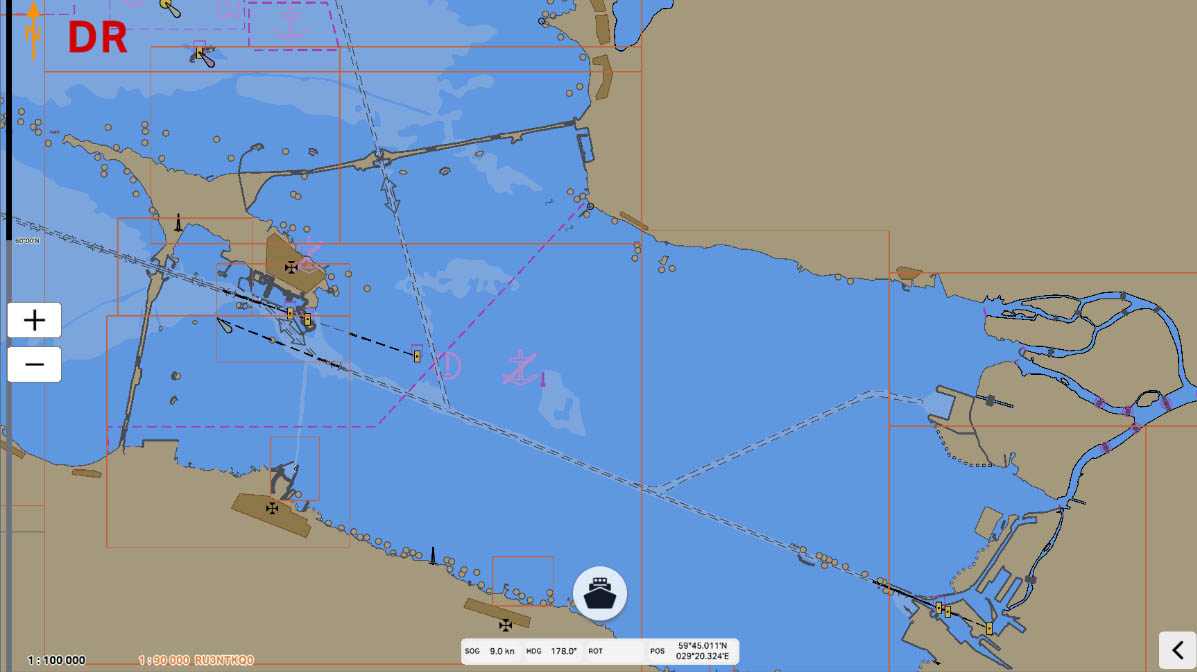
This panel displays LAT, LON, HDG, SOG, Next COG, BTW data.
You can swipe the panel to left or to right to change a display mode.
- LAT: Latitude
- LON: Longitude
- HDG: vessel’s Heading
- SOG: vessel’s Speed-Over-Ground
- Next COG: Course Over Ground to the next route point
- BTW: Bearing-To-Waypoint (to the Active WP)
You can swipe the panel to left or to right to change a display mode.
NAV info bar
6


Planned Speed (P.SPD, in knots) setting is available in the Planning Mode. Speed is adjustable manually for all route legs and will be taken into ETA calculation in the Sailing mode (Current SOG will be used for rest legs and ETA calculations, as previously). P.SPD value for the current leg is selectable in the Top Navigational Bar and in the Sailing mode panel.
Current route information
8


11. The "Search" button is one of the main elements of the ECDIS interface. It allows the user to quickly find the necessary information on electronic navigational charts.
12. The Routes button opens the routes panel, allowing access to route planning, editing, and management tools.
This feature can be useful for:
13. To navigate to the AIS Targets panel, click the AIS button. This panel provides real-time information about nearby vessels equipped with AIS, helping to enhance situational awareness and improve navigational safety.
14. To navigate to the ENC panel, click the ENC Atlas button. This panel provides access to the list of installed Electronic Navigational Charts (ENCs), allowing you to manage, view, and update chart data for safe and efficient navigation.
12. The Routes button opens the routes panel, allowing access to route planning, editing, and management tools.
This feature can be useful for:
- Quick navigation – providing easy access to all saved routes.
- Route adjustments – enabling modifications to existing routes as needed.
- Efficient voyage planning – helping to organize and optimize planned passages.
13. To navigate to the AIS Targets panel, click the AIS button. This panel provides real-time information about nearby vessels equipped with AIS, helping to enhance situational awareness and improve navigational safety.
14. To navigate to the ENC panel, click the ENC Atlas button. This panel provides access to the list of installed Electronic Navigational Charts (ENCs), allowing you to manage, view, and update chart data for safe and efficient navigation.
Basic Program Control Buttons
11
12
13
14
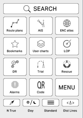
15. To go to the Bookmarks panel, click the Bookmarks button on the main panel. This section allows you to quickly access saved locations or important points on the map for easier navigation and reference.
16. To navigate to the User Charts panel, click the User Charts button located in the block of main buttons on the main panel. This section allows you to create, manage, and display custom charts, enabling personalized navigation and additional mapping options.
17. To navigate to the LOP Observation panel, click the LOP button located in the block of main buttons on the main panel. This section allows you to perform Line of Position (LOP) observations, aiding in accurate position fixing and improving navigational precision.
Basic Program Control Buttons
15
16
17
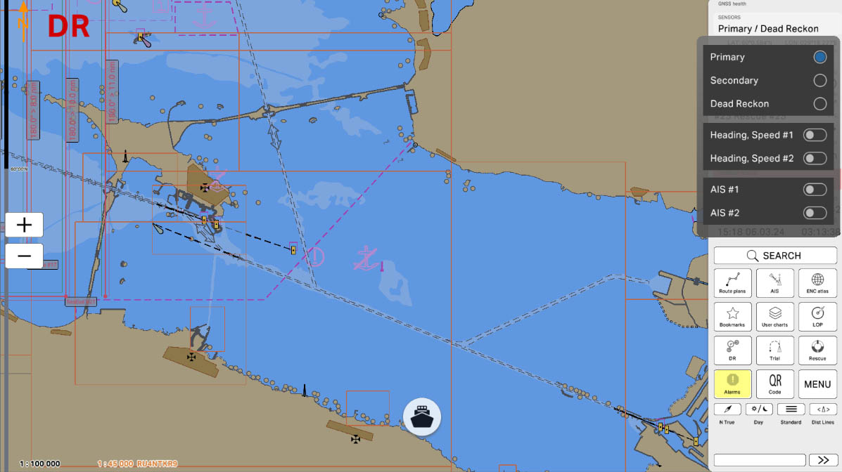
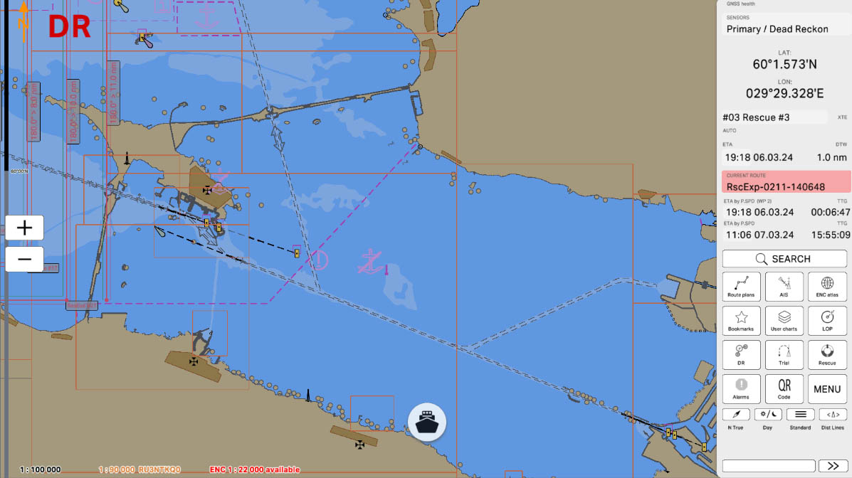
18. Press the DR button in the navigation panel to display the special pad control for Dead Reckoning (DR) correction. This tool allows you to manually adjust the estimated vessel position based on heading, speed, and time, ensuring more accurate navigation in situations where GPS data is unavailable or unreliable.
19. Press the Trial button on the navigation panel to open a special control pad for trial maneuvering in operational mode with the connected sensor. This feature allows you to simulate planned course changes, assess potential maneuvers, and evaluate their impact on navigation before executing them in real conditions.
20. The Rescue button opens the Planning the Search panel, where you can configure settings for a search operation in case of a man overboard incident. This panel allows you to set parameters for an organized search pattern and mark the exact location where the incident occurred. The marked point will be fixed on the map, providing a visual reference for navigation and coordination during the rescue operation.
Basic Program Control Buttons
18
19
20
21. Alarm Button is a crucial feature in the ECDIS system designed to alert the crew to various warnings and alarms.
Alarm Button is designed to instantly alert the crew to arising issues or potential hazards. In case of a warning, the button flashes yellow, indicating the need for attention and possible action. If a critical issue arises, the button flashes red, demanding immediate action to prevent a dangerous situation.
22. This QR Code button opens a set of QR codes, allowing you to scan them using your phone’s camera. This feature provides a quick and convenient way to transfer all necessary data for registering your device and vessel on ecdis-link.com, significantly simplifying the process of purchasing electronic charts for ECDIS. Additionally, it enables you to retrieve a list of installed ENCs on your device and share planned routes efficiently.
23. The MENU button opens the context menu, providing access to various program settings, such as sensor settings, ship settings, ENC settings, safety settings, program preferences, and profile configurations.
Basic Program Control Buttons
21
22
23
24. Chart orientation. The settings change the alignment of the chart. Tap N True / Course up / Heading up button in the toolbar:
25. Palette button. The 'Palette' button is designed to switch between the 'Day', 'Dusk' and 'Night' palette.
26. Display Category. The settings define how many data will be draw on a chart (there are three IMO categories and customized for the chart display - Basic, Standard, Full and Custom).
27. The Distance Lines button opens a panel where users can configure distance measurement parameters according to the requirements and conditions of the specific navigational situation.
Basic Program Control Buttons
24
25
26
27


The "3.5. Navigation Panel" section has been completed.
Success!